The following chapters describe the functionality of each editor group and the single pages per button. It does not explain the synthesis engine of the VL1. This text will grow, whenever I have time for it.
Connect to Power
Connect the controller to a power supply at the back side connector. It is not included in my delivery, because it is hard to match them to your local standards. You have to use a DC 7-9V power supply, 5.5mm plug, plus in the middle. Here are examples on Amazon and Thomann:
Riot DC Power 9 Volt – Musikhaus Thomann
You should prefer these power supplies, if you intend to mount the controller into a rack. But you can also connect a USB power supply using the Micro USB cable through the small hole at the top. You must be careful, unfortunately the Micro USB is a very sensible plug:
- Connect only in unpowered state (other side not connected to power supply or PC)
- If you connect the USB cable, please be careful to insert it in the right direction. Match the painted whit dots, that I painted onto the later devices. Do not plug the Micro USB cable into the controller upside down else this will brick the device.
- The plug must snap in and make a silent ‘click’. If not then something went wrong.

The USB cable will also be used to upgrade the firmware via a PC or Mac.
General Tips
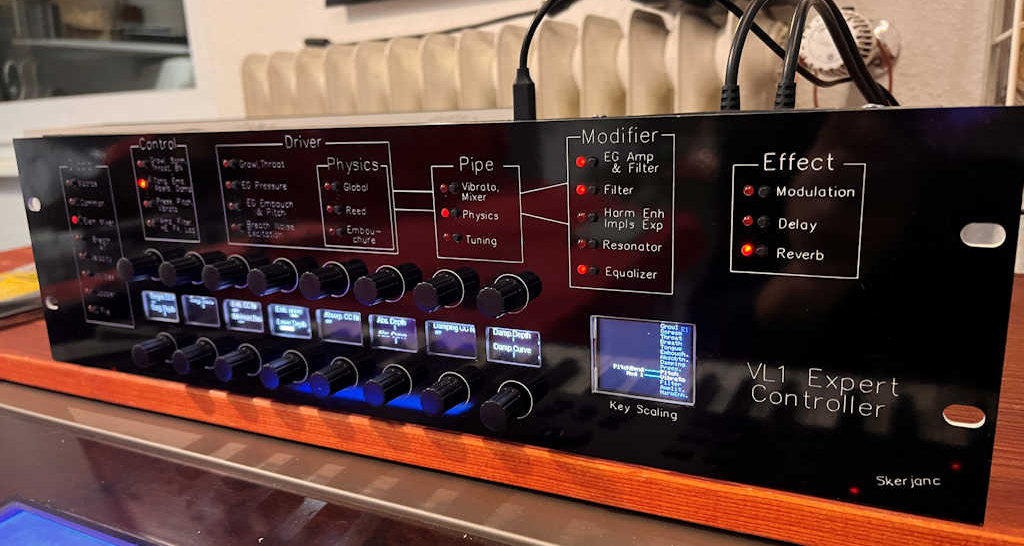
The fundamental concept for users is to select the desired function block by pressing the button next to the titles. An LED light indicates the selected page. You may observe that multiple LEDs can simultaneously emit a dim light to draw attention to certain pages, such as when a reverb effect or resonator is active.
The compact OLED screens display the names of the parameters that can be adjusted by the encoders. The upper half of the screen corresponds to the top encoder, and vice versa. The grid-based endless encoders then adjust the value, which is displayed as a bar and a numerical value.

Some parameters are dealing key numbers & names. In that case, you can additionally use the VL1 keyboard or another MIDI keyboard to select the key as well. However you have to turn the knob first to focus the key detection to that parameter.
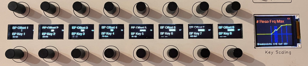
Some parameter names have a trailing dash ‘#’ which indicates that it supports key scaling. If you press that encoder, you enter the key scaling mode: The lower row of encoders then select the key number and the upper row the offset value to this parameter. If more than 8 breakpoints are supported by this parameter, a press on a lower button switches the view to the next page. You will also see “Breakpoints 9-16 (of 16)” on the colour screen.
The OLED display will go into sleep mode (get dark) after some time of inactivity.
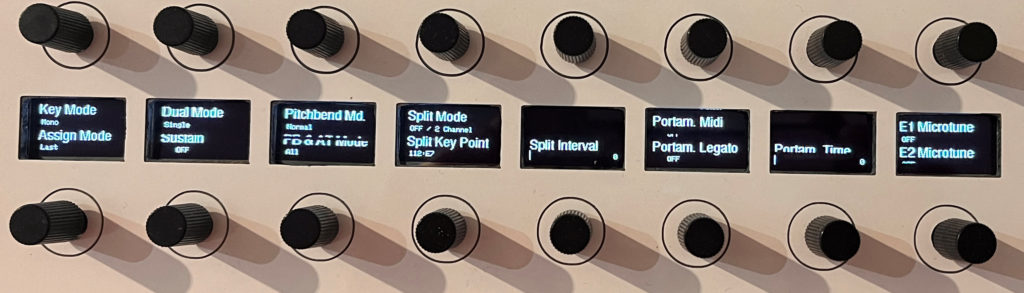
The Pages of Global Block

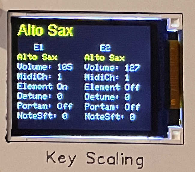
After power-on the current patch will be loaded from the VL1 and shown here. If the VL1 is off or the MIDI connection is wrong, then the display will show the current firmware version and a warning about a failed SYSEX response from the VL1.
When you change to a new program on the VL1, then the controller will detect this and request the transmission of the patch.
Macros
The controller allows morphing between two elements E1 and E2, that means the model is linearly transformed from one instrument to the other. It is accomplished by sending interpolated parameters as you turn the “Morph E1<>E2” encoder or use a CC control data from your keyboard. The control number is selected with the dial “Morph CC Nr”. E1 and E2 can be loaded separately, e.g. “File>Load E1->E2 only”.
Given the multitude of VL1 parameters, the MIDI interface can easily become overwhelmed by the necessary SYSEX messages. Our approach is to temporarily halt the transmission of morphed data while the CC controller is in motion, and resume data transmission once the CC controller has ceased activity. Further you can reduce the areas of the model to be morphed exclusively to these blocks: Physics, Pipe Driver, Modifier.
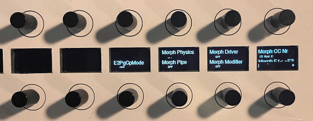
An additional experimental technique involves duplicating selected controller pages from E2 to E1. When ‘E2PgCp Mode’ is activated, the controller enters a unique mode: pressing any of the page knobs of Driver, Physics, Pipe or Modifier groups triggers a transfer of all E2 parameters on that page to to E1. If the outcome is not to your liking, you can revert to the previous state using Utility>Undo.
Remember to deactivate all morph features once you’ve completed the morphing process.
Common
You have the option to modify both the voice name and the names of the elements E1 and E2 here. Rotate the encoder to a letter position, then press the button to select a different character. Pressing the button a second time will complete the editing of this character.
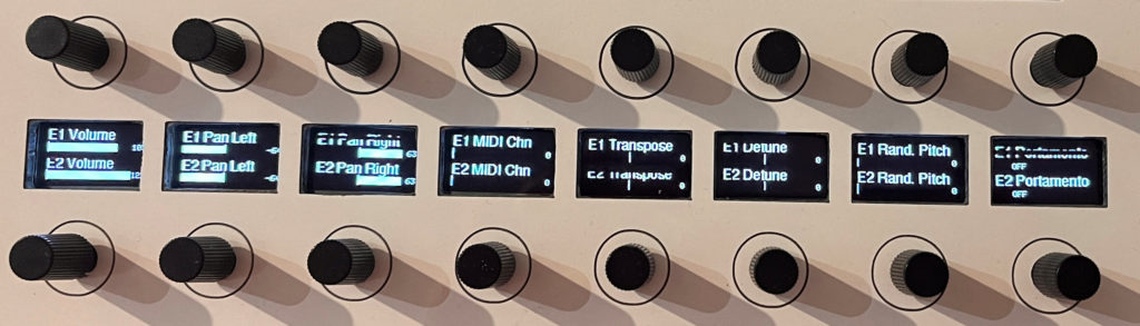
Element Mixer
Breath, AT

Velocity
Same as above for parameters controlled by velocity.

Utilities

You can specify the device number that the VL1 responds to. Beneath this encoder, you can select either element 1 or 2 for modification. The active element for editing is always indicated by a red E1 or E2 at the top right corner of the TFT display.
This page also features an undo function: when you enter a parameter page, its previous content is saved and can be restored by this function. Above this encoder you can select to have Help Texts shown on the TFT display when you are in the physical model pages.
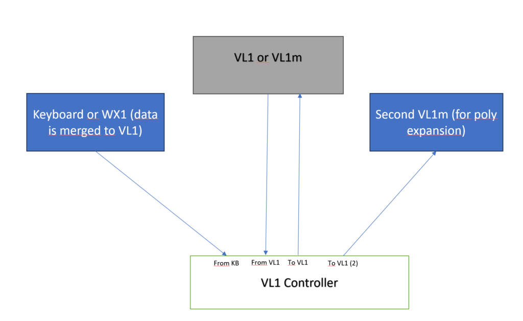
You can enhance the controller by adding a second VL1m, which allows for 4-voice polyphony and simultaneous editing of voices on both devices. Connect the 4th MIDI out, labeled ‘To VL1(2)’, to the VL1m.
Navigate to the Utilities page and activate the ‘Poly Expansion’ option. After waiting a few seconds, you’re all set! All configurations are automatically adjusted, and the modified voice is transferred to the second device.
When a new program is chosen on the primary VL1, this patch is automatically sent to the second VL1. Remember to reactivate ‘Poly Expansion’, as this setting is part of the voice. This setup demonstrates the utilization of all four MIDI connections:
Looper
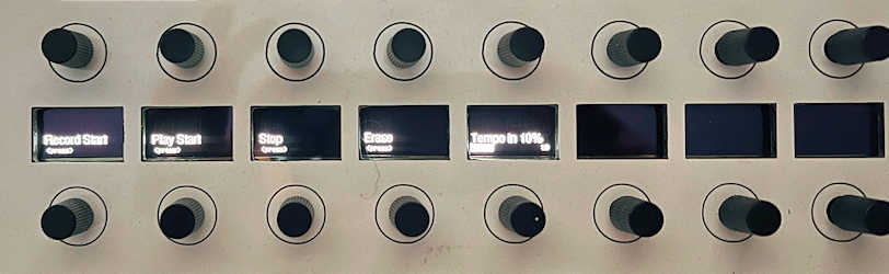
This page features a straightforward yet effective polyphonic MIDI looper. You can record any MIDI events such as notes, CC, and pitchbend from the VL1 or KB input jacks and loops them back. While the loop is playing, you can navigate to other pages and continue editing the voice. Playback may be interrupted when big SYSEX dumps are transmitted at the same time.
To start recording, press the RECORD button and begin playing, then press STOP when you’re done. Pressing PLAY will loop the recording until you press STOP. If you press RECORD while playing, it goes into overdub mode and you can play additional notes or controller movements on top. There’s also an ERASE button to delete the current recording, and you can adjust the playback speed by turning the “TEMPO IN %” button from 50 to 200% in steps of 10.
The TFT displays the current state along with playing time in Minutes:Seconds, the recorded events and free memory. When memory is used up, the recording automatically stops. The loop content will be erased when you turn off the controller.
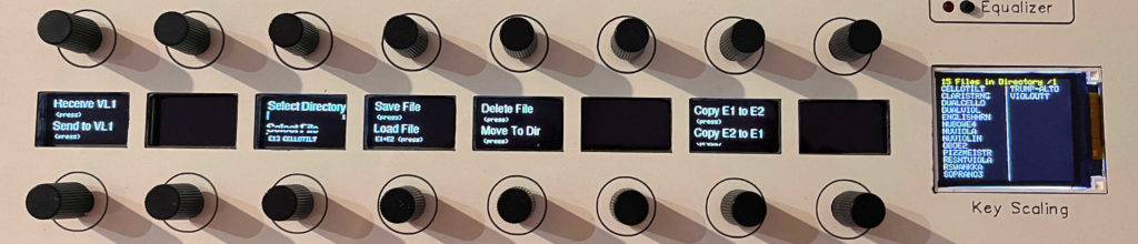
File
When you select a new voice on the VL1, it will automatically send it to the controller. You can also manually receive or send patches to the VL1. On this page are also functions to save and load patches to the internal SD card. Currently you can select between 20 directories to store your patches. You can also load single elements (E1 or E2) to any destination, and an element could be internally copied to the other.
The Pages of The Control Block

The VL1 can control 16 destinations by any arbitrary MIDI-CC control number. These destinations are divided into 4 pages. The colour display gives an overview which controller is assigned to a destination. Unused destinations appear grey.

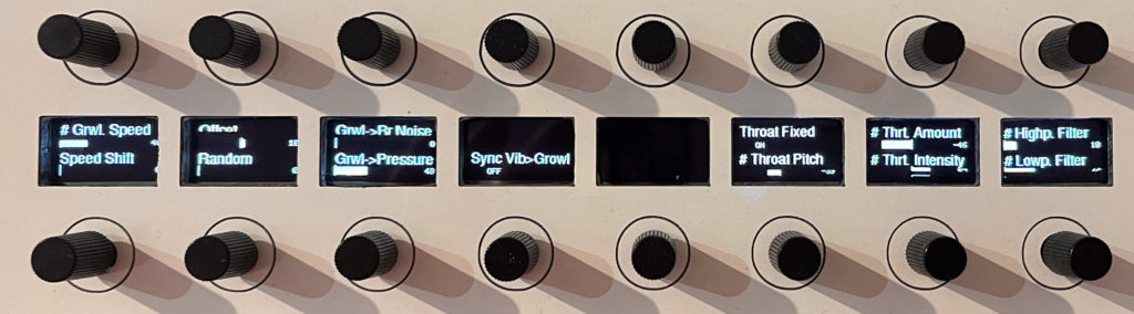
The Pages of The Driver Block

Growl, Throat
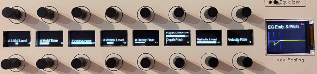
Pressure EG

Embouchure EG
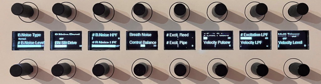
Breath Noise, Excitation
The Pages of Physics Group
These pages delve into the intricacies of the internal model. It’s crucial to comprehend the workings here, as any modifications could lead to silence, chaos, or detuned instruments. I recommend reading the invaluable “VL Programming Guide” by Manny Fernandez for further understanding. Each parameter from this document displays a brief help text on the color display when activated. Despite the number of these parameters, they are well-organized, and you will eventually gain an overview. If the help screens are not needed or are causing distraction, you can disable the help display on the Utility page.

Global
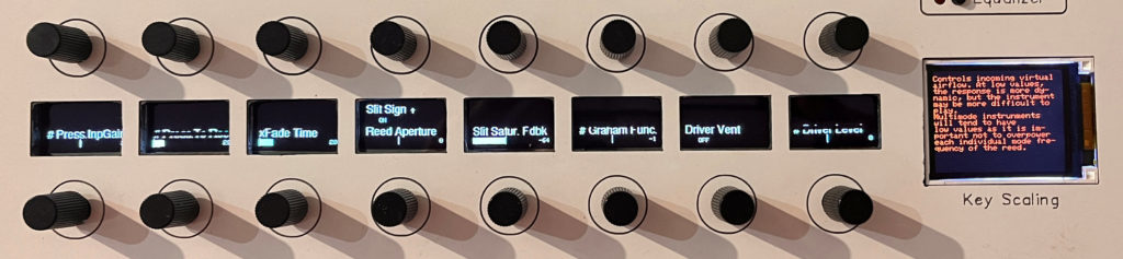
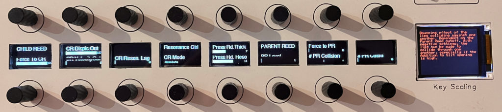
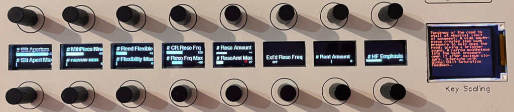
Reed
Embouchure
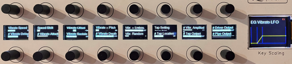
Vibrato, Mixer
Pipe Physics: when you select Straight Insert to ON, you will enable the new parameters for straight and conical inserts introduced in VL1 Version 2. The image on the TFT display changes according the inserts are modified. Green parts means the length are tracked by the played key, if they are in white, they are static.

Tuning: This page allows you to tune the entire model. I suggest to start experimenting with the Tuning Mode ‘1 Key’. You’ll need to use an external tuner, select a key with ‘Select Key’ by rotating the encoder or playing a note on the keyboard, and then tune it with ‘Tune Key’. The TFT display presents the key numbers on the x-axis and the pipe length on the y-axis as a white curve. The blue lines serve as guides to modes (or overtones), with higher modes represented by lower lines.
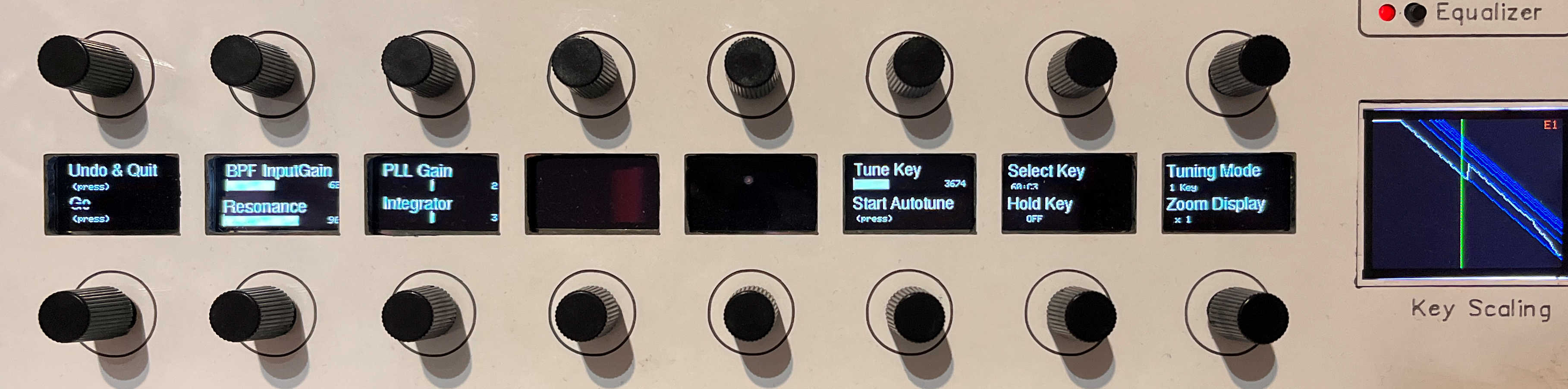
Instead of manually tuning the pipes, you can press “Start Autotune”, to tune one key using an automated process. The settings of the autotune algorithm like BPF InputGain, Resonance, PLL Gain and Integrator are set by default to the values suggested by Manny and need no change normally.
In the Tuning Mode “Autotune Range” you will get more comfort. Do first an “Initialise” to calculate an estimate tuning curve to the desired modes within certain ranges (possibly experiment with Multiplier), then let the system fine tune all keys between “From Key” up to “To Key” by pressing “Start Autotune”. The following steps depend on the setting of “CR Resonance Control” on the Reed page.
Child Reed Resonance Control = Absolute:
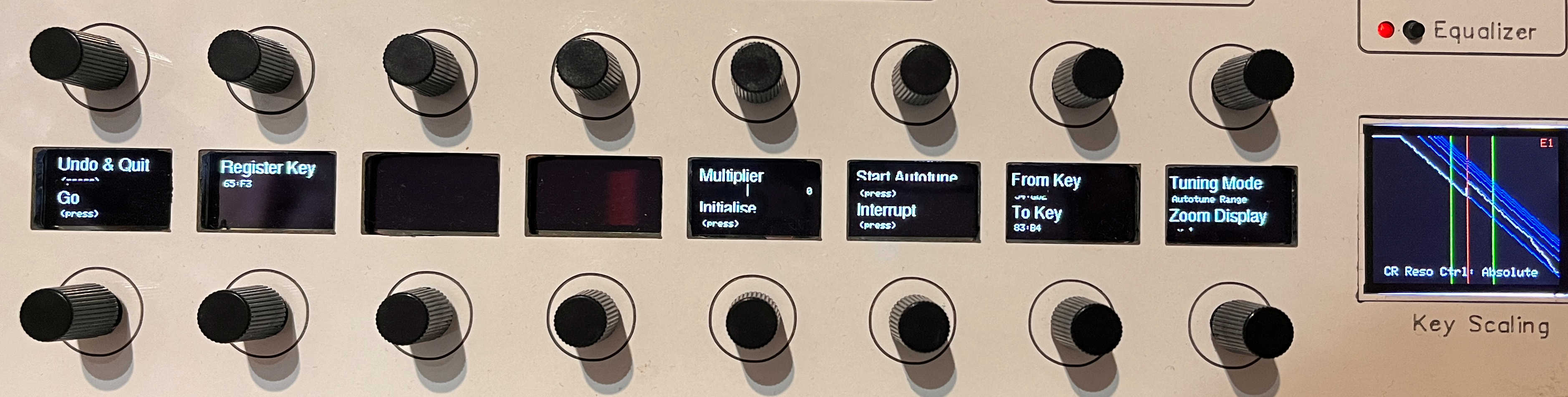
If set to “Absolute”, only two modes exist and depend on the Register Key. The value “Multiplier” determines the overtone for the 2nd mode. 0 corresponds to first octave, 63 the second. Press “Initialise” to estimate an initial tuning curve as starting values for the subsequent autotune process.
Child Reed Resonance Control = Relative:

This multimode setting allows the initialisation of 3 breakpoints to select the keys where to change modes. Select the keys on the “Mode I-III Key” encoders and tune them to the desired mode lines and press “Initialise”.
When you are done with all the tuning, press “Go” to leave this page and finalise the tuned instrument on the VL1. If you are not satisfied and want to leave with the old state, press “Undo & Quit”. Do not change to other pages without that, as the VL1 is still waiting in the tuning mode and will not response properly.
The Pages of Modifier Group

EG Amp & Filter
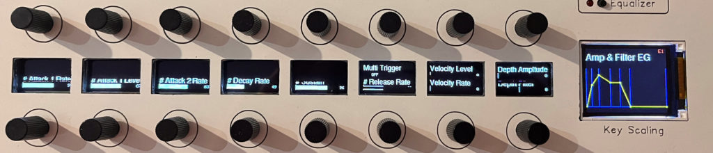
The LED lights dim, if the EG depth to filter is other than zero.
Filter

The LED lights dim, if the filter has some wet ratio.
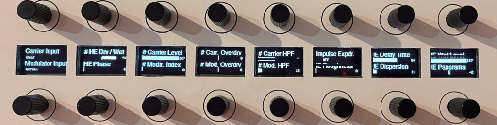
Harmonic Enhancer & Impulse Expander
The Harmonic Enhancer (HE) is a crucial and efficient component. It’s the ideal starting point for significantly altering the sound without modifying the model. Initially, consider changing the Carrier or Modulator input types or adjusting the overdrives.
Note that the dimmed LED will indicate if the Impulse Expander (IE) is activated on this page.
Resonator
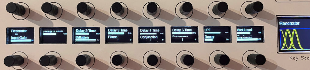
The LED lights dim, if the resonator has some wet ratio.
Equalizer

The LED lights dim, if any EQ level is other than 0dB.
The Pages of Effect Group
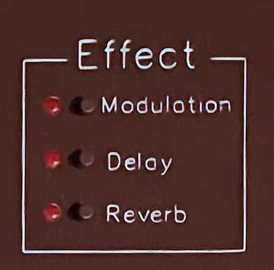
Effects
All effect parameters are fully accessible here. The corresponding effect LED glows when the effect is active.
Modulation

Delay

Reverb
